Page 1 of 3
MiL Mi-1
Posted: Mon Dec 02, 2019 2:56 pm
by RangerNeil
Total newbie at this, not having built models for over 30 years, so - in typical fashion - have started at what some here already think might be the deep end.

(there is an existing thread on this model one here at
viewtopic.php?f=37&p=340512#p340512)
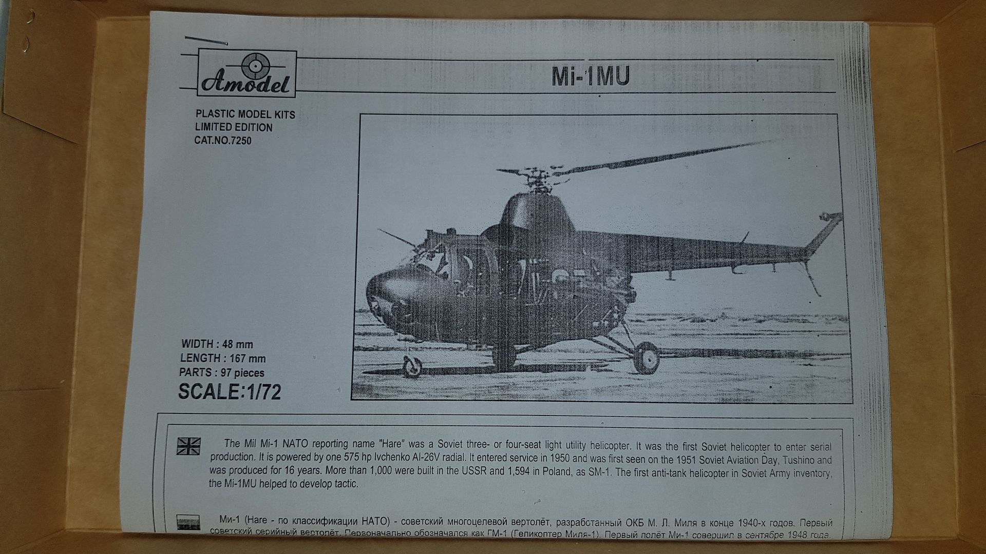
The kit is the AModel MiL Mi-1 MU (NATO code name "Hare") the first production Soviet helicopter that first flew in prototype form in 1948 and entered service with the VVS and PVO-Stranyy in 1951, remaining in service with continual improvements until 1965. It was also used by the State airline Aeroflot. By the end of production it was in use by 23 countries. Initially a 3 seater later ones with a more powerful engine had the capacity increased to carry 4. In the West the contemporary machines were the Bristol Sycamore and the Sikorskky H5.
The kit itself is of the Mi-1 MU - a variant meant to armed with either 4 x "Falanga" or 6 x "Malyutka"anti-tank missile systems. As far as is known it never got past the prototype stage.
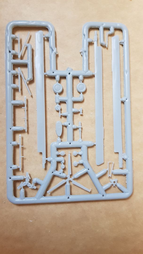
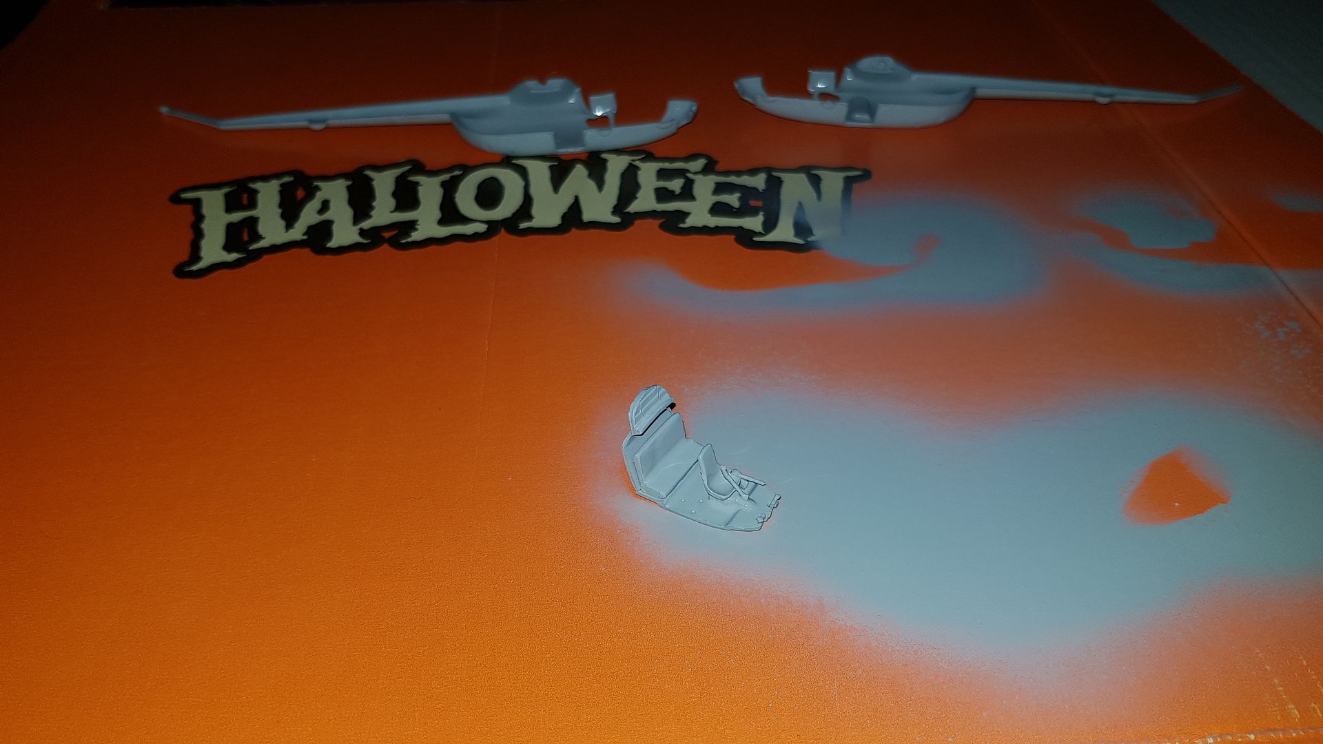
Inside the box there are 4 part sprues, a clear sprue, decals and the instruction sheet as shown below.
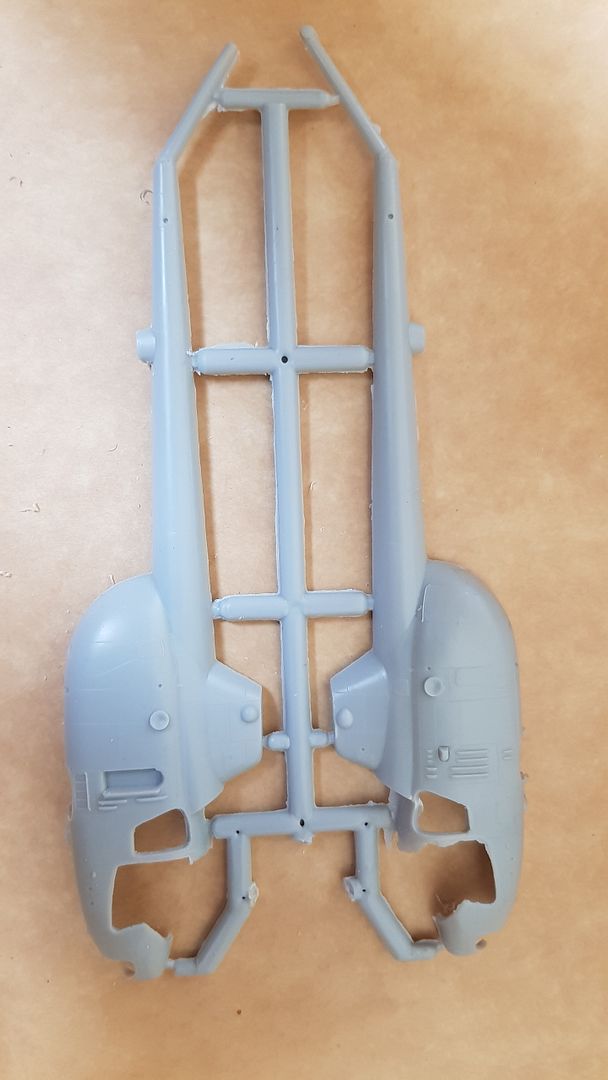
Fuselage halves.
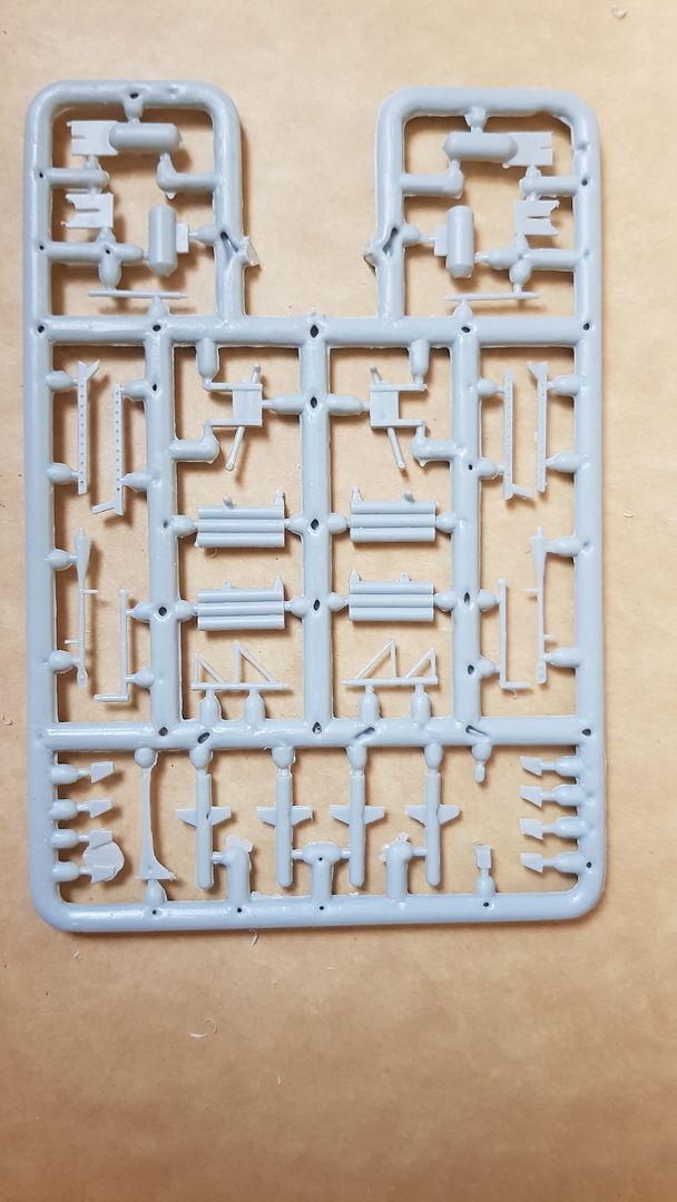
Falanga and Malyutaka missile systems.
Rotors and undercarriage.
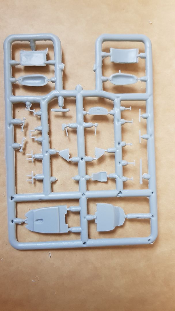
Cockpit interior and exterior fittings.
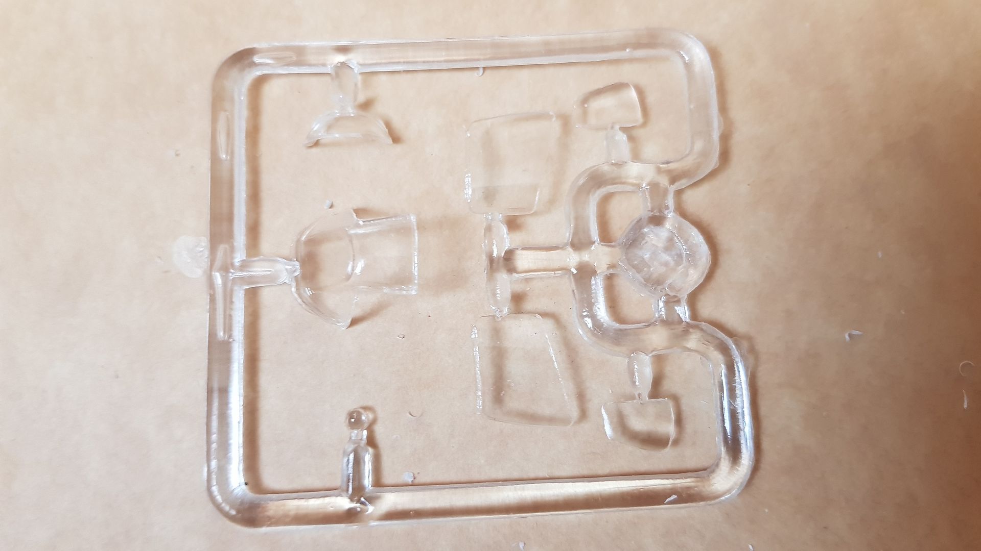
Clear parts.
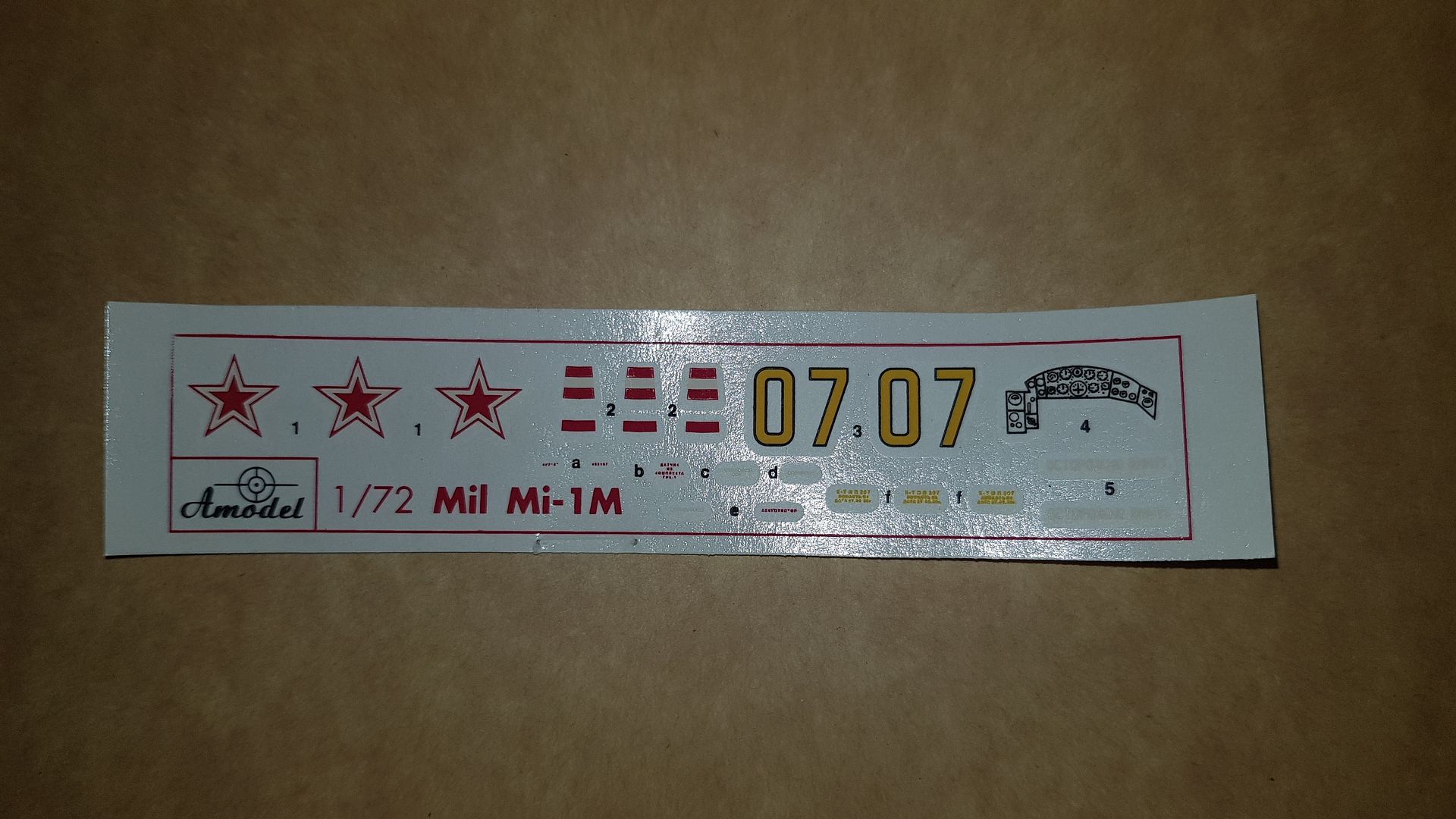
Decals.
Instruction sheet.
I should point out the sprues were photographed AFTER I had removed a lot of the excess flash - it looked for all the world like the two halves of the mould had not closed properly - so I hope that is acceptable for this build??
Compared to Amodels editions of the Mi-6, Mi-10 and Mi-12 this is quite crude in both terms of the mouldings and the instructions so I assume it was one of their early editions. The instruction sheet looks like a photocopy rather than a professionally printed sheet. But it is readable so that all thats necessary I guess. We are moving home in Q1/Q2 of 2020 so I did not want to start on any of the bigger ones in the stash.
The kit itself looks to be an "interesting" build as there are very very few locations pins or indents in the fuselage halves so locating things like the undercarriage and missile systems will be challenging to say the least.
Oh well - fingers crossed!!
Re: MiL Mi-1
Posted: Mon Dec 02, 2019 3:29 pm
by Tomcat64
Welcome to the Hovering SIG mate - great to have you onboard (especially with those deliveries you've had recently

)
Looks like you might have your hands full tidying this one up but looking forward to seeing you tackle it

If you have any questions about how the SIGs work then feel free to drop them into a post or ping me a PM and I'll help out as best I can.
Re: MiL Mi-1
Posted: Mon Dec 02, 2019 3:54 pm
by jmurphy18
Cool looking model Neil. Enjoy the build
Re: MiL Mi-1
Posted: Mon Dec 02, 2019 6:33 pm
by Twokidsnosleep
Interesting and VERY different
Best of luck with the build

Re: MiL Mi-1
Posted: Mon Dec 02, 2019 6:53 pm
by Kevthemodeller
Very interesting kit, good luck with the build mate
Re: MiL Mi-1
Posted: Mon Dec 02, 2019 9:24 pm
by digger303
fingers crossed it all works out
Re: MiL Mi-1
Posted: Tue Dec 03, 2019 1:07 am
by RangerNeil
For the sake of simplicity - and my fingers
- all future posts on this build will appear here - until the 4 months is up...
So - had another stab tonight. First off all the sprues were washed in warm water with a dash of the soapy stuff to clean any release agent off - please to note the high-tech working environment, use of which got my wife muttering the D word again!!

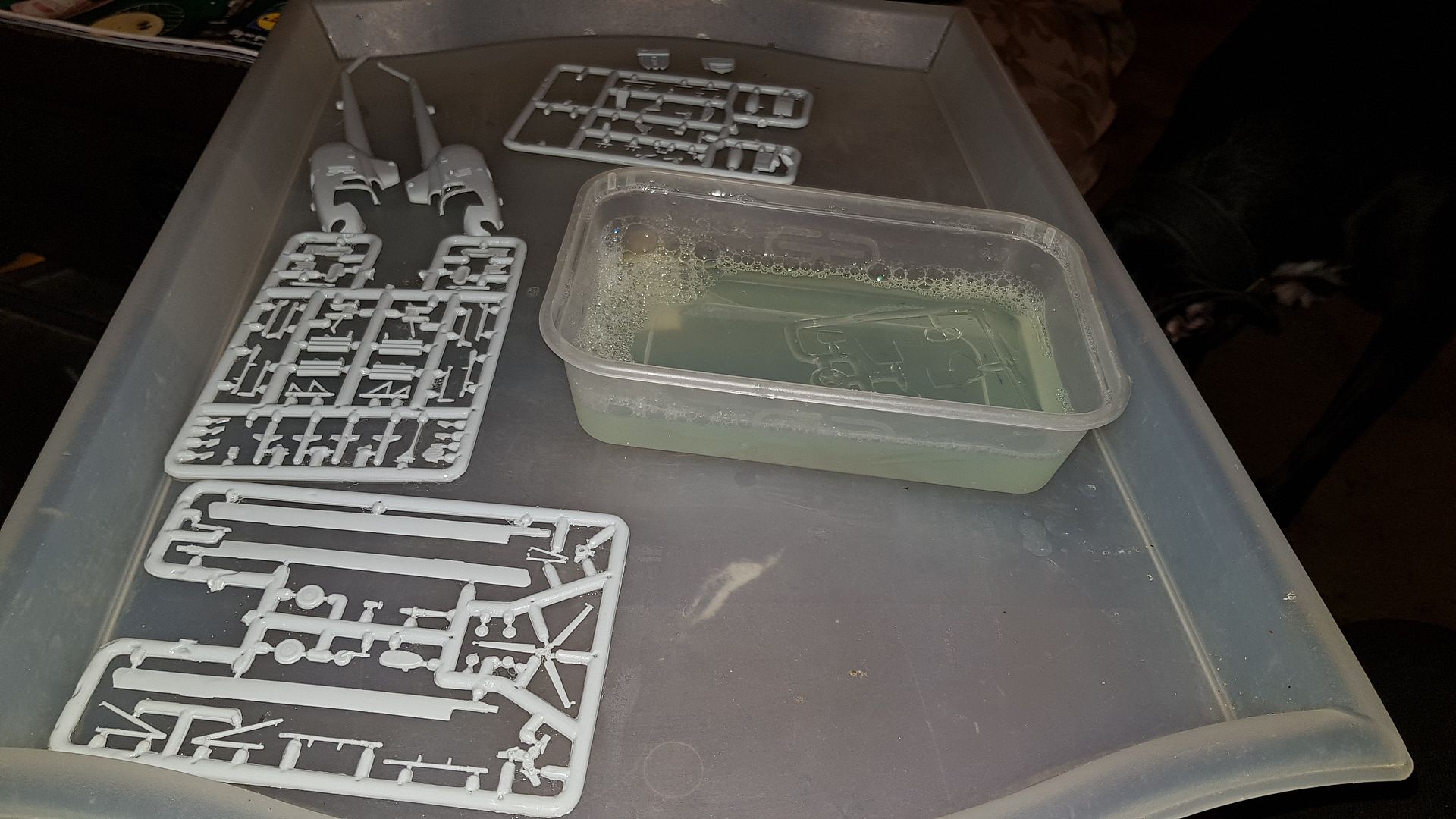
Having scrubbed the parts I retract a part of what I said last time. VERY close examination reveals that there are slight indentations in the fuselage where the main undercarriage is meant to to go, a flashed over hole where the nose wheel goes - and some small marks inside that need to be drilled if the missile systems are to be attached. Needless to say I am quite pleased about that!!
Once the parts were dried off I removed the cockpit floor and rear bulkhead from the relevant sprue as well as the two fuselage halves. It may seem an odd thing to do but - the bulkhead has to sit back at an angle, not vertical so they were joined by a strip of masking rape and placed into one fuselage half. The other half was then juggled into place and the two joined by pieces of masking tape as you can see below.
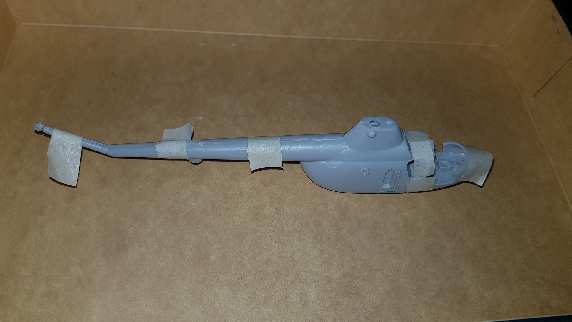
You can see - just - in the third picture where one of the headaches is going to be when I finally come to using the adhesive to join the two halves. The cabin roof immediately in front of the rotor mast has a hell of a gap when everything else is joined. By the simple expedient of offering up the cockpit front/roof section its apparent that with the gap closed up its just the right width for the clear section - so the issue will be closing it up without messing up the rear bulk head. You also see that what I took to be a head-rest in the rear bulkhead is acutually the intake grill for the engine... That will teach me to jump to conclusions!!
A plus point - as you see in photo #2 there is a large hole in the base of the fuselage where a stick can be inserted and used to "wiggle" the blukhead into the correct position once the two halves are joined. Eventually this gets filled by what looks like an exhaust vent....
This is about as far as I can go at the moment - the paint sets (AKAN acrylics) that are an exact match to the Soviet colours are in transit from a store in Moscow and until they get here I am stymied. Once they arrive I can paint the cockpit, I/P and fuselage interior as well as the seats, rudder pedals, joystick and collective - then the cockpit can be assembled and the fuselage halves mated together and what I recall as being the enduring joy of sanding the seams smooth can begin.

Re: MiL Mi-1
Posted: Tue Dec 03, 2019 9:50 am
by Stokesy44
All the best for the build mate.
Nice subject, real quirky
Re: MiL Mi-1
Posted: Tue Dec 03, 2019 10:19 am
by Tomcat64
Blimey you're cutting plastic already - I'm still just looking at the instructions on mine
Looks like there might be some slight adjustments to make there - are you able to get some plastic sheet or something up behind that bulkhead gap to help with the filling?
Re: MiL Mi-1
Posted: Tue Dec 03, 2019 10:30 am
by digger303
Your making me cringe with talk of gaps and pieces not coming together...
Re: MiL Mi-1
Posted: Tue Dec 03, 2019 2:36 pm
by jmurphy18
Neil, I am with Digger on the gaps and the not fitting .....;


Looking good so far and you are leaps ahead of me here!! I do have you beat on the washing as I am the one who does the dishes
. I use the big deep sink in the kitchen and the strainer to dry. LOL. Especially as I am retired and she is still at work
HAGD
Re: MiL Mi-1
Posted: Tue Dec 03, 2019 9:28 pm
by Kevthemodeller
Re: MiL Mi-1
Posted: Tue Dec 03, 2019 9:40 pm
by TommyKillander
That's a really cool subject

Best of luck with the build!
Tommy
Re: MiL Mi-1
Posted: Wed Dec 04, 2019 12:18 am
by RangerNeil
Tomcat64 wrote: Tue Dec 03, 2019 10:19 am
Blimey you're cutting plastic already - I'm still just looking at the instructions on mine
Looks like there might be some slight adjustments to make there - are you able to get some plastic sheet or something up behind that bulkhead gap to help with the filling?
In fairness- I've been looking at the instructions for this one for a fews days prior to the build starting
As for the gap - right now I am not sure - thats the best I can say. If you look at the last of the photos below you can see the worst area in front of the rotor pillar.
digger303 wrote: Tue Dec 03, 2019 10:30 am
Your making me cringe with talk of gaps and pieces not coming together...
Such is life...
I really, really hope to God the Mi-6, -10 and -12 are a lot better than this one. Otherwise I am in for the mother of all nightmares x 3. Especially the Mi-12 as a chunk of it is fibre-glass.

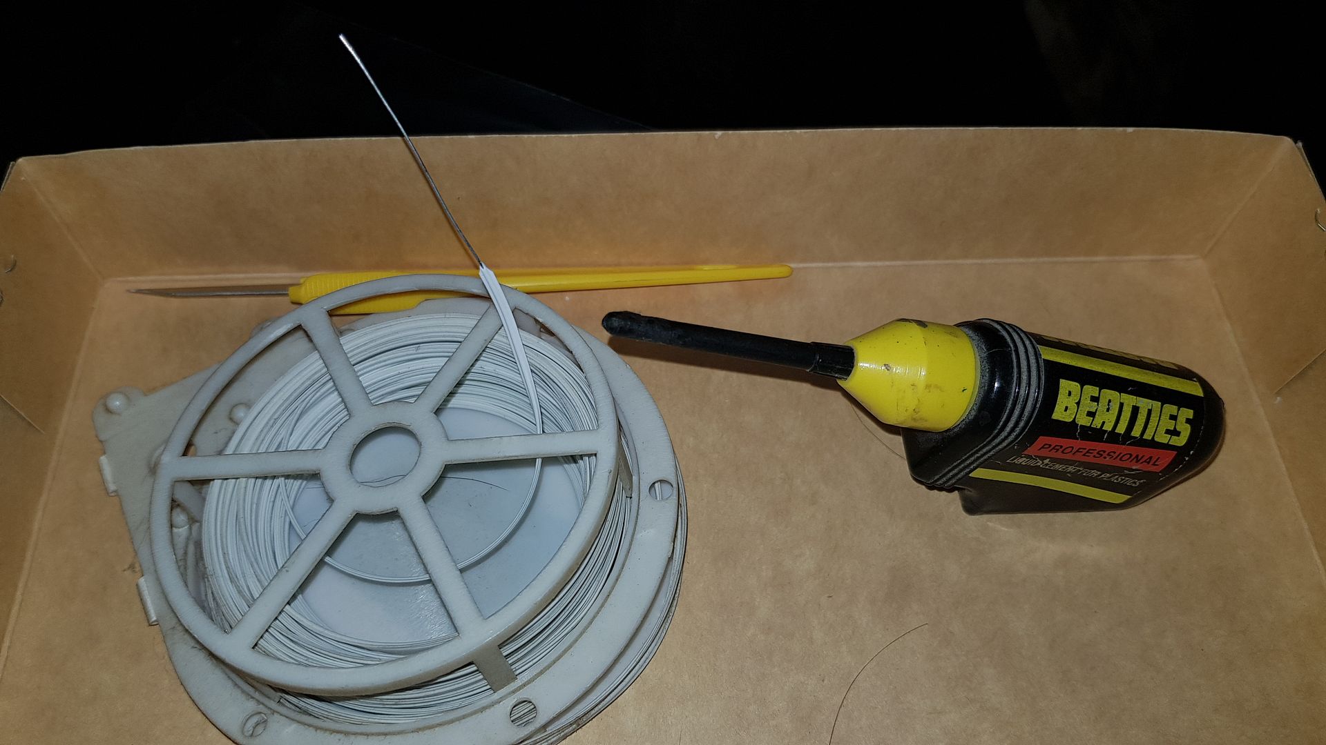
But on to today..... Lost most of the day in "discussions" with the Post Office over the contents of a package that contained paint sets but got a bit more done tonight. A major leap forwards - for me - was finding the long-lost bottle of liquid cement! Then finding a high tech way of unblocking the applicator!!
Don't laugh too loud - it worked!!
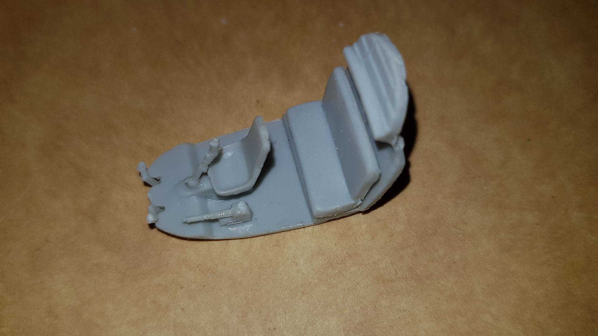
Having done that I moved on to the cockpit assembly stage. The floor and buklhead had liquid cement applied whilst they were held in place between the fuselage halves and this was allowed to set for an hour. The two halves were then seperated and the rest of the cockpit components fitted. Took quite a while as the only thing that fitted straight in was the rudder pedal assembly. Both the front and rear seats needed more of the excess flash removed and the front seat had a square peg beneath it that was meant to locate in a square hole in the cockpit floor. No prizes to the ones who say "bet it didn't"!
Took a bit of careful shaving and carving to get it to fit properly. Rear seat also needed a fair bit of sanding to the base to get it to sit flat on the raised step on the cockpit floor. The collective and control column needed very careful trimming to remove both the flash remnants and the cut-off points from where they were attached to the sprue. I am noticing that all the fine parts have VERY thick attachment points compared to, say, Tamiya or Hasegawa or even Trumpeter. However eventually every thing was trimmed and placed. I took the decision to assemble it raw and then paint completely afterwards. I think it was the right move despite not being what I am used to doing. Tomorrow I will give it a coat of primer - if Halfords grey cellose is suitable? - then a couple of coats of the right grey from the AKAN kits. If not then painting will have to wait until I can get a can of Tamiya or similar.
To finish the night off I moved onto the rotor shaft. I can then assemble the fuselage halves once the cockpit is painted. Again a simple operation that turned out a wee bit more complicated than first met the eye. To start with - the captive plate that sits in the rotor pillar looked to have a hole through it - until it was turned over.. The hole did not go all the way through.... So I measured the hole dia where it existed with a set of calipers and put that size drill though. Then looked at the shaft. It was obvious it could only go one way - but in the instructions it was drawn symetrical..... Doh!!!
Took a fit of jiggery pokery to work out which was the right way around which then revealed the hole was actually too small.... So a bit more fine work took place to persuade the shaft to fit throught the hole. The captive piece was then cemented onto the end of the shaft and the plate into one side of the rotor pillar.
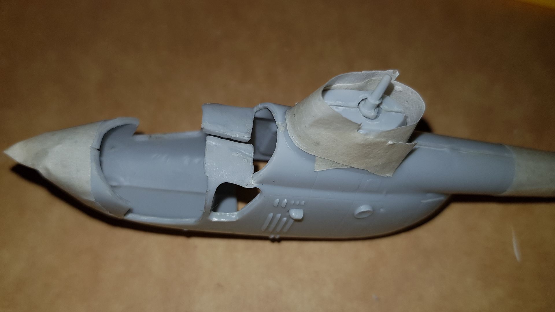
The pillar was not taped tightly in case of cement squeezing out but you can see very plainly in this shot the gap in the cockpit roof... I am thinking - going by the front edge - that its not a case of shrinkage but one of the pieces is slightly warped so once everything is ready for the fueselage halves to be permanently joined a good clamp will correct this. I want to verify this by dry-fitting the cockpit glazing once the fuselage is ready to be tightly taped up. It should be interesting.

Re: MiL Mi-1
Posted: Wed Dec 04, 2019 2:06 am
by digger303
RangerNeil wrote: Wed Dec 04, 2019 12:18 am
Tomcat64 wrote: Tue Dec 03, 2019 10:19 am
Blimey you're cutting plastic already - I'm still just looking at the instructions on mine
Looks like there might be some slight adjustments to make there - are you able to get some plastic sheet or something up behind that bulkhead gap to help with the filling?
In fairness- I've been looking at the instructions for this one for a fews days prior to the build starting
As for the gap - right now I am not sure - thats the best I can say. If you look at the last of the photos below you can see the worst area in front of the rotor pillar.
digger303 wrote: Tue Dec 03, 2019 10:30 am
Your making me cringe with talk of gaps and pieces not coming together...
Such is life...
I really, really hope to God the Mi-6, -10 and -12 are a lot better than this one. Otherwise I am in for the mother of all nightmares x 3. Especially the Mi-12 as a chunk of it is fibre-glass.
But on to today..... Lost most of the day in "discussions" with the Post Office over the contents of a package that contained paint sets but got a bit more done tonight. A major leap forwards - for me - was finding the long-lost bottle of liquid cement! Then finding a high tech way of unblocking the applicator!!
Don't laugh too loud - it worked!!
Having done that I moved on to the cockpit assembly stage. The floor and buklhead had liquid cement applied whilst they were held in place between the fuselage halves and this was allowed to set for an hour. The two halves were then seperated and the rest of the cockpit components fitted. Took quite a while as the only thing that fitted straight in was the rudder pedal assembly. Both the front and rear seats needed more of the excess flash removed and the front seat had a square peg beneath it that was meant to locate in a square hole in the cockpit floor. No prizes to the ones who say "bet it didn't"!
Took a bit of careful shaving and carving to get it to fit properly. Rear seat also needed a fair bit of sanding to the base to get it to sit flat on the raised step on the cockpit floor. The collective and control column needed very careful trimming to remove both the flash remnants and the cut-off points from where they were attached to the sprue. I am noticing that all the fine parts have VERY thick attachment points compared to, say, Tamiya or Hasegawa or even Trumpeter. However eventually every thing was trimmed and placed. I took the decision to assemble it raw and then paint completely afterwards. I think it was the right move despite not being what I am used to doing. Tomorrow I will give it a coat of primer - if Halfords grey cellose is suitable? - then a couple of coats of the right grey from the AKAN kits. If not then painting will have to wait until I can get a can of Tamiya or similar.
To finish the night off I moved onto the rotor shaft. I can then assemble the fuselage halves once the cockpit is painted. Again a simple operation that turned out a wee bit more complicated than first met the eye. To start with - the captive plate that sits in the rotor pillar looked to have a hole through it - until it was turned over.. The hole did not go all the way through.... So I measured the hole dia where it existed with a set of calipers and put that size drill though. Then looked at the shaft. It was obvious it could only go one way - but in the instructions it was drawn symetrical..... Doh!!!
Took a fit of jiggery pokery to work out which was the right way around which then revealed the hole was actually too small.... So a bit more fine work took place to persuade the shaft to fit throught the hole. The captive piece was then cemented onto the end of the shaft and the plate into one side of the rotor pillar.
The pillar was not taped tightly in case of cement squeezing out but you can see very plainly in this shot the gap in the cockpit roof... I am thinking - going by the front edge - that its not a case of shrinkage but one of the pieces is slightly warped so once everything is ready for the fueselage halves to be permanently joined a good clamp will correct this. I want to verify this by dry-fitting the cockpit glazing once the fuselage is ready to be tightly taped up. It should be interesting.
I here a glint of hope in your post, but I'm cringing even more from that pic.....
Re: MiL Mi-1
Posted: Wed Dec 04, 2019 4:14 pm
by Tomcat64
Now that's some scary looking "alignment" issues! It actually looks from the photo like the parts may have been warped by heat somewhere along the years.
Really looking forward to seeing how you beat this into submission though.
Re: MiL Mi-1
Posted: Thu Dec 05, 2019 12:25 am
by digger303
Re: MiL Mi-1
Posted: Thu Dec 05, 2019 3:32 pm
by jmurphy18
Looking good! Nice job on the kit build
Re: MiL Mi-1
Posted: Thu Dec 05, 2019 5:22 pm
by RangerNeil
Thanks for the kind words all. First time building in over 30 years so a LOT has changed.
Gone as for as I can on the fuselage/cockpit until I can paint the cockpit. I was looking at using ordinary cellulose primer as I had nothing else - but thinking on it the pigment might be a bit too coarse for 1/72 and, whilst pondering, had an e-mail from eModels mentioning Tamiya primer spray - so I ordered a can + some masking tape (another new fangled idea
Delivery is due tomorrow.
So tonight I will have a look at the missile systems.
Re: MiL Mi-1
Posted: Fri Dec 06, 2019 9:48 pm
by RangerNeil
A small -literally - update tonight.
Whilst I was waiting for the primer tonight I got on with the four Malyutka A/T missiles. For reasons best known to AModel they split the missile fins so the two in line with the sprue are moulded as part of the missile whilst the two at right angles were moulded separately.
Problem 1 was separating the 8 fins from the sprue whilst preserving the shape as the connectors were bigger than the parts.
Problem 2 was holding the fins to clean them up. Tiny fins and big fingers are not a happy combination - one went flying whilst being sanded and it was all hands and eyes to the floor to find it. Luckily we did.
I wrapped masking tape around ahead and behind the moulded fins to act as guides then placed the fins on one side and set aside to dry for an hour
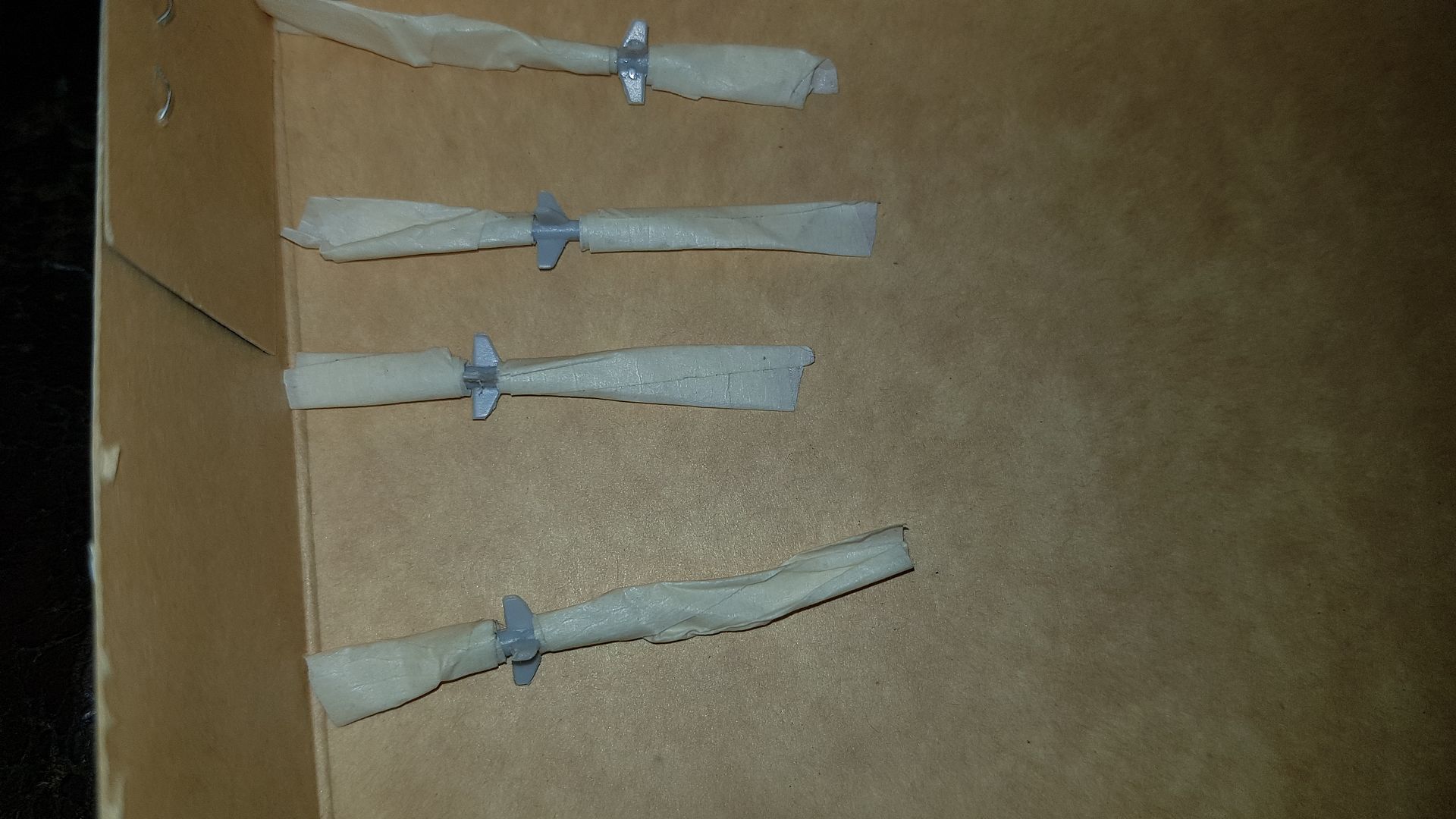
Then added the other 4 fins - now drying and awaiting a coat of primer. Meantime I am trying work out how the launcher rails go together and then onto the fuselage...
Re: MiL Mi-1
Posted: Sat Dec 07, 2019 4:38 pm
by RangerNeil
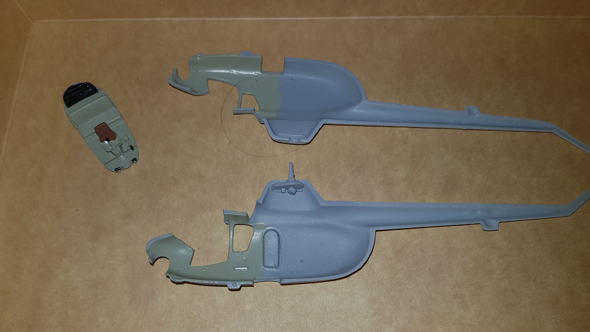
Gave the fuselage interiors and the cockpit assembly a coat of Tamiya primer today. In keeping with the hi-tech build facilities to date - note the highly advanced paint booth!! Best described as a flattened cardboard box on top of a camping table in the spare room.
It worked - apart from the issue of fume extraction. No one could go upstairs for over an hour - which caused a slight problem as the loo is upstairs. Cue unhappy wife.... Again...
Now first to try and find a decent paintbrush then work out which of the greys in the AKAN sets is the right one for the Mi-1's cockpit. Never used acrylics before so a new experience is about come my way..
Re: MiL Mi-1
Posted: Sat Dec 07, 2019 5:02 pm
by jmurphy18
looking good Neil
Re: MiL Mi-1
Posted: Sat Dec 07, 2019 7:27 pm
by RangerNeil
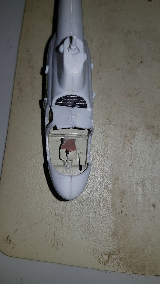
Aaand - the fuselage halves and upper cockpit are now painted. Once its all dry the cockpit needs to be flipped over andthe floor given a coat as it will ve visible through the nose glazing.
Yet another first for me - frst time I ever tried using acrylic paint. The Mi-1 predates the colour swatches AKAN have for the Soviet helicopters (at the moment) so the nearest I could get by matching paint to images of various Mi-1's on the web was the faded grey normally used on the outside of things like the Mi-6 and Mi-10.
The back of the pilots seat was done in Humbrol enamel as I don't have an acrylic for that colour. Yet.
This gets left to dry overnight then tomorrow the underside of the cockpit floor gets a coat of the grey too as its visible through the lower nose glazing.
A close examination of the inside of the fuselage reveals more little holes that go nowhere. The ones around the middle rear are for the weapons racks - there are three different ones supplied with the kit and its up to the builder to determine which ones are needed. The instructions do not cover this at all. There are also some at the front below where the cockpit doors are located. I think these are for the steps and perhaps small antenna. I need a more detailed study of the instructions to determine if they need opening up. If they do then - obviously - I need to do this before assembling the fuselage halves together.
As a interim review of the kit thus far - its definitely NOT one for a beginner and AModels state this on the box. At first I thought they were over-stating things but I am coming to realize that they are being factual. Things go along comparatively easily for a while - leaving aside the issues of excessive flash, alignment and thickness of the sprue attachment points - then you come to something that has you going "what the hell". I'm enjoying the challenge (and in no way claiming to be an "experienced" modeller) but I would not recommend it to someone starting out in the hobby.
There is a classic example of this to come when the main rotor is assembled....
Re: MiL Mi-1
Posted: Mon Dec 09, 2019 1:34 am
by RangerNeil
Initial joining of fuselage halves done tonight - not the easiest of tasks with no locating pins anywhere. I decided in the end to build this as a straight Mi-1 and not the -MU variant with A/T missiles.
I still have to address that mis-alignment ahead of the rotor mast. But to do that I need to find a way of clamping it. Clothes pegs are too small, tape won't hold and neither would the elastic bands I tried. I have a set of toolmakers clamps somewhere so I'll dig them out, wrap the jaws in tape then try them.
Next thing to fit is the instrument panel. The instruction sheet just says apply the decal to the part - but as you see below there is a big difference between the decal and the part so I am assuming the extra bits on the decal wrap around to the inside of the fuselage.......
Re: MiL Mi-1
Posted: Mon Dec 09, 2019 3:15 pm
by Tomcat64
More good progress in knocking this monster into shape
Great save on fetching the missile fin back from the carpet monster... but you're on your own with the irate wife!!!
Re: MiL Mi-1
Posted: Mon Dec 09, 2019 11:35 pm
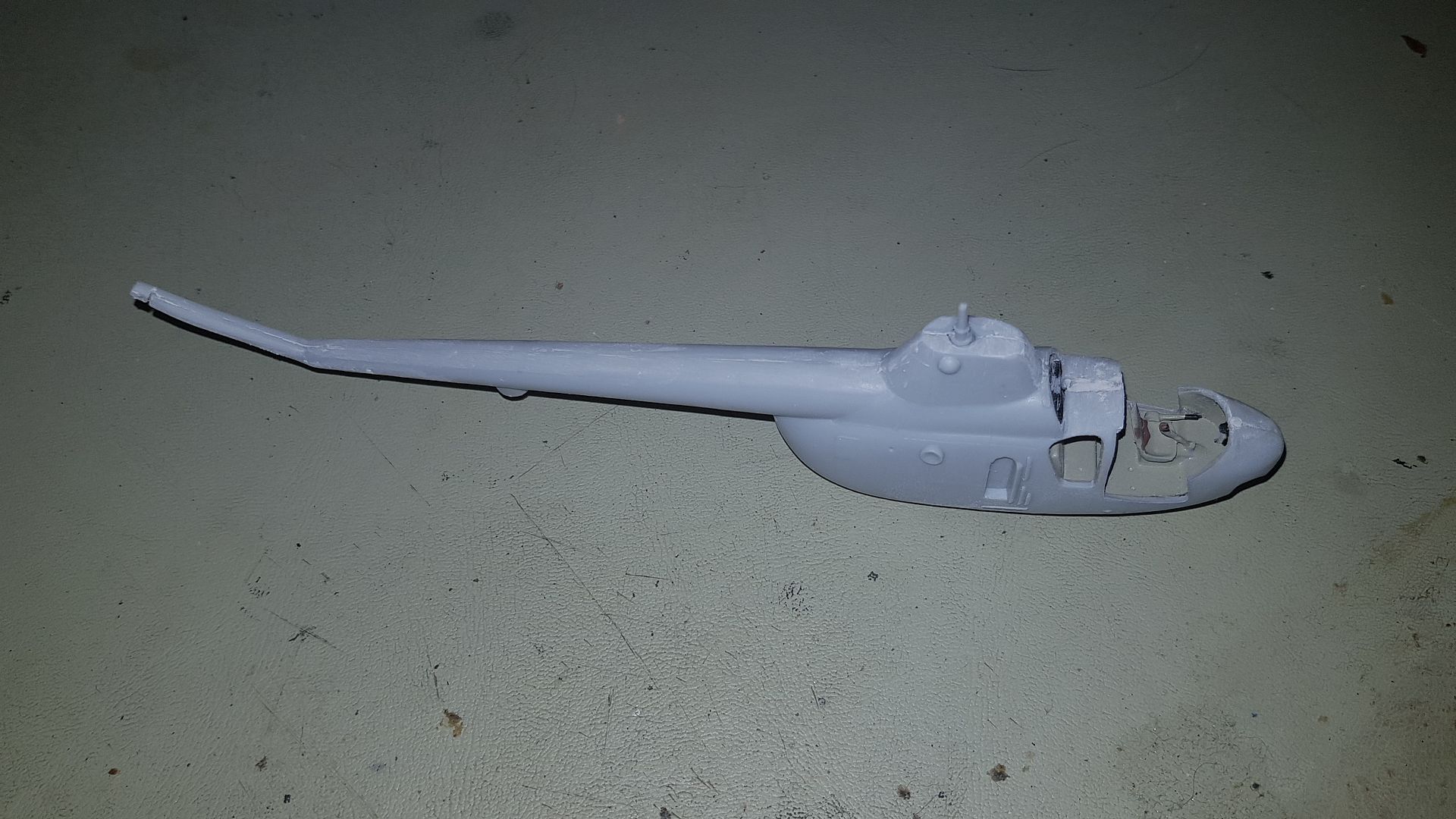
by RangerNeil
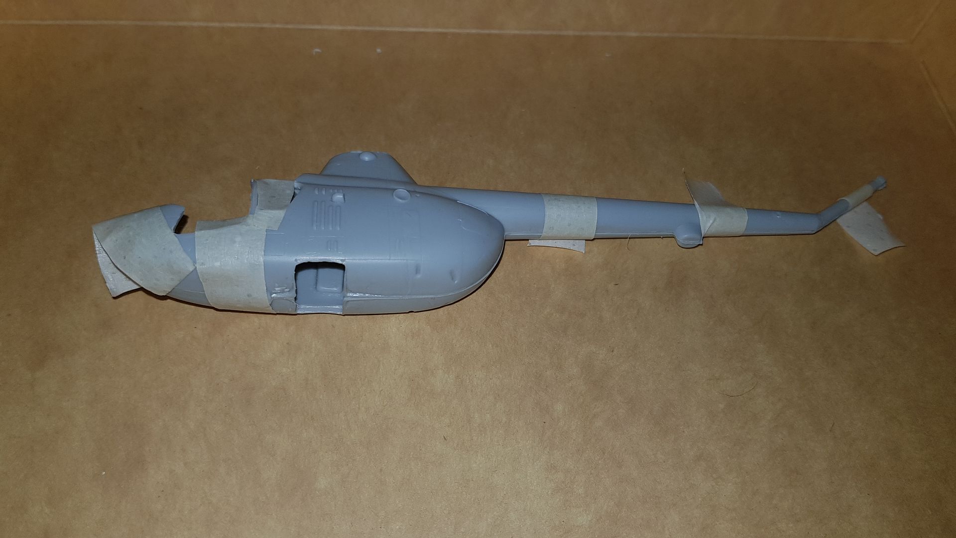
Joined the fuselage halves last night - tape and clamps are off now and this is the result thus far. The seams have been trimmed and lightly sanded but more to do there I think before I put a light coat of primer onto make sure its a good finish:
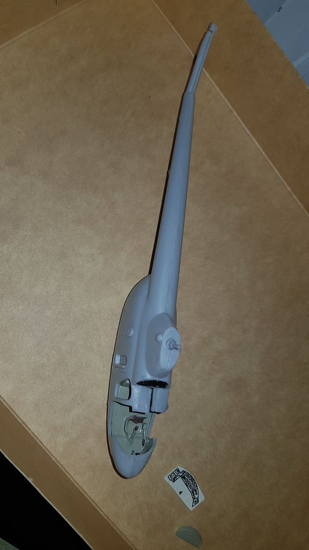
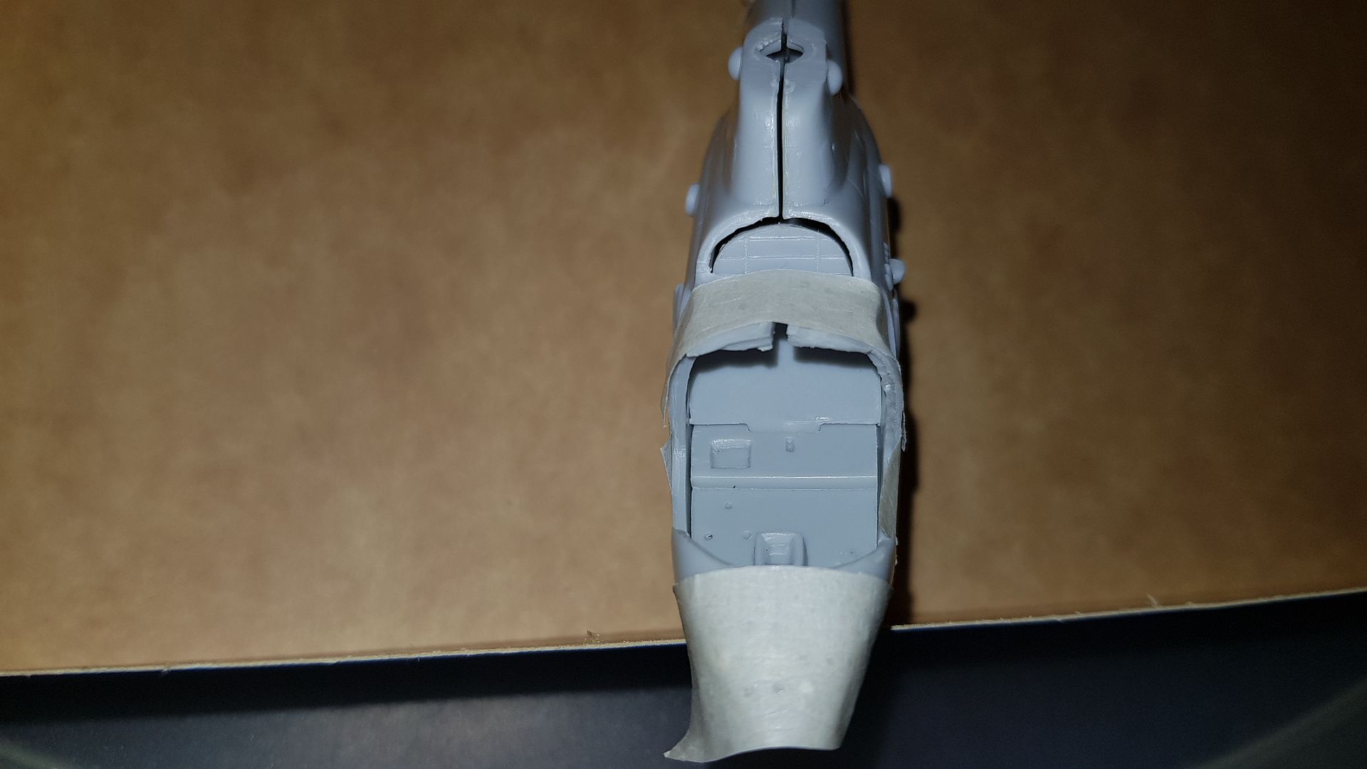
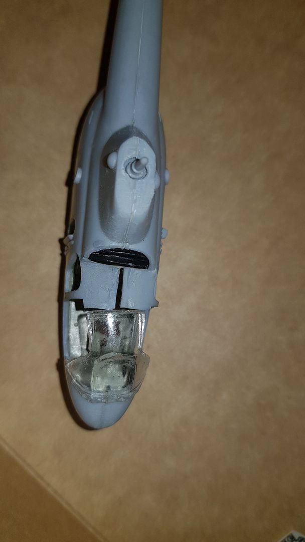
The first of the issues can be clearly seen there - the rather severe lack of alignment on the cockpit roof:

I placed the canopy roughly in position so it looks very much like the sections have spread rather than anything else. Trying to find an old toolmakers clamp (from the days when I did that for a living) which hopefully will both squeeze the two sections to gether and allow a bit of fine adjusting to get the join in the centre of the canopy.
And - unbelievably - I never noticed the screw-up on the paint in the pilots seat. Think I need a trip to SpecSavers! So before the canopy ever goes on this needs rectifying. For some odd reason there is no seat cushion on the Mi-1 - the pilot got to wear a parachute, The passengers didn't. Which gives rise to two interesting questions:
1) What the hell were the passengers supposed to do in the event of the pilot bailing out?
2 How was the pilot supposed to get clear of the rotors of a maachine falling a LOT faster that he was..?
Whilst its true the Russian mind tends to think outside of the box for a lot of things (
try asking the design team for the BMP who got shipped to Afghanistan to rectify the shortcomings in the BMP-1...) - sometimes they can jump from the box into the frying pan!!
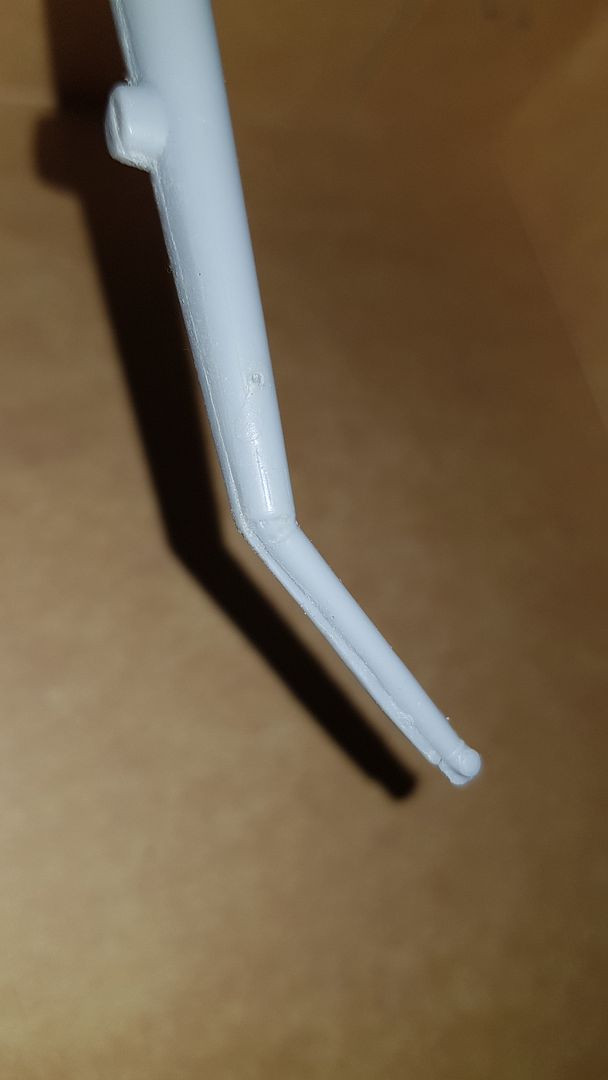
The other one - which was avoidable sadly - was the tail rotor boom slipped a litle when it was clamped. I see two routes here - either I trim the sides down and up with a thinner and thus weaker tail rotor or - and this is what I favour at the moment - building up the back-side with a little filler and sanding back to the right form. This will give me the correct proportion rotor boom.
Re: MiL Mi-1
Posted: Tue Dec 10, 2019 3:24 pm
by jmurphy18
Re: MiL Mi-1
Posted: Tue Dec 10, 2019 11:12 pm
by digger303
When coming up against this type of problem in the future I'm going to do what a fellow modeler here does and glue some guides to the inside wall of the molds. It seems like a good solution.
Re: MiL Mi-1
Posted: Wed Dec 11, 2019 4:37 am
by KalebB
Great job bud!
She's coming together for sure.
As for the comments on the BMP-1, that got quite a chuckle out of me
Re: MiL Mi-1
Posted: Wed Dec 11, 2019 5:17 pm
by RangerNeil
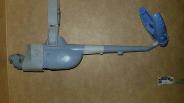
Does this class as over-kill??
Re: MiL Mi-1
Posted: Wed Dec 11, 2019 9:07 pm
by jmurphy18
ROTFLMAO. I think it might be a bit of overkill
.
Re: MiL Mi-1
Posted: Wed Dec 11, 2019 10:52 pm
by digger303
Re: MiL Mi-1
Posted: Thu Dec 12, 2019 12:23 am
by RangerNeil
Well - overkill or not - it worked....
Re: MiL Mi-1
Posted: Thu Dec 12, 2019 5:43 am
by KalebB
Ain't no such thing as overkill as long as it gets the job done haha
Re: MiL Mi-1
Posted: Thu Dec 12, 2019 2:35 pm
by jmurphy18
Awesome Neil. This gives the adage where there a will there is a way!
Me I am learning the hard way build helo's as this is my 1st and probably building Axx backwards LOL!

Re: MiL Mi-1
Posted: Thu Dec 12, 2019 4:23 pm
by Twokidsnosleep
Wow that is a big gap
If it is really open like that, you can take a flat piece of styrene and TET it in between the open joint to help close the space.
It will close it up and have less strain to prevent it from wanting to pop open again.
Just have to make sure the canopy still fits right
Re: MiL Mi-1
Posted: Thu Dec 12, 2019 8:08 pm
by Quax

Its fighting but you're beginning to win, keep going!

Paul
Re: MiL Mi-1
Posted: Thu Dec 12, 2019 10:25 pm
by RangerNeil
Thanks for the kind words everybody. I confess to being worried about how it would go after not having touched a kit in decades.....
Twokidsnosleep wrote: Thu Dec 12, 2019 4:23 pm
Wow that is a big gap
If it is really open like that, you can take a flat piece of styrene and TET it in between the open joint to help close the space.
It will close it up and have less strain to prevent it from wanting to pop open again.
Just have to make sure the canopy still fits right
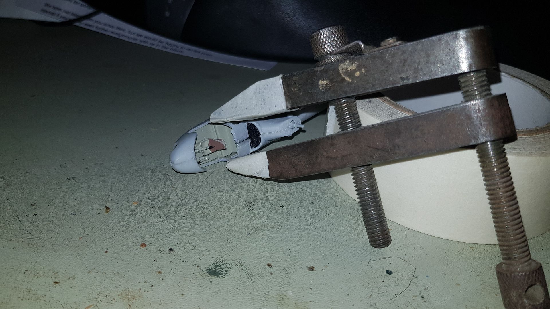
I offered up the cockpit glazing to see how it stacked up against that roof area and it was obvious the the two sides needed to be squeezed together to line up with the sides of the glazed roof, I could not get away with just filling the gap. Hence the rather large clamp. Its a toolmaker's clamp so will clamp at funny angles with as little or as much pressure as you want.
Hit a hiatus on the fuselage tonight - I needed modelling putty like Milliputt to rework the tail rotor boom - and haven't got any. So a question: what's people recommendation these days for putty/filler??
And what's the recommended adhesive for cockpit glazing?? Normal polystyrene? Or is there now a special one?
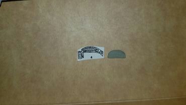
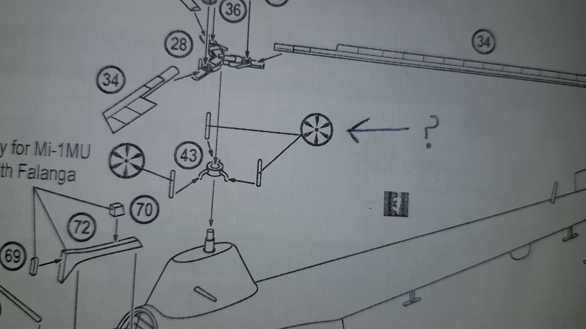
Lastly for tonight - does anyone recognize the symbol arrowed in the photo below??
I wanted to crack on with the main rotor head but that symbol is not listed on the instruction sheet and I've never seen it before!!
Re: MiL Mi-1
Posted: Thu Dec 12, 2019 10:57 pm
by digger303
Clear glazing..
varnish
tet...permanent bond...use just a touch and test a bit first.
PVA ...Soft adhesive
Various companies do a clear fixative.
Do not use Ca.
Sprue glue...melted sprue ( melted in tet )can be used, but takes a while to set. Advantage being it is plastic and is easily shaped. Can melt tiny details.
Tamiya putty...not a favorite among many
delux materials ...plastic magic...best if surface is lightly roughened first. Can be smoothed and reactivated with water....best with smaller problems.
Re: MiL Mi-1
Posted: Thu Dec 12, 2019 11:44 pm
by RangerNeil
digger303 wrote: Thu Dec 12, 2019 10:57 pm
Clear glazing..
varnish
tet...permanent bond...use just a touch and test a bit first.
PVA ...Soft adhesive
Various companies do a clear fixative.
Do not use Ca.
Sprue glue...melted sprue ( melted in tet )can be used, but takes a while to set. Advantage being it is plastic and is easily shaped. Can melt tiny details.
Tamiya putty...not a favorite among many
delux materials ...plastic magic...best if surface is lightly roughened first. Can be smoothed and reactivated with water....best with smaller problems.
Many thanks
Looks like I will be investing in a bottle of tet much earlier than expected. To show how old most of my stuff is - the bottle of adhesive is marked "BEATTIES Professional liquid cement for plastics". I forget how many years its been since the Beatties chain went under, must be getting on for twenty or so...
Hmmm - I think I may also have some PVA floating about. Does it need diluting or use straight from the bottle??
Re: MiL Mi-1
Posted: Fri Dec 13, 2019 10:37 am
by digger303
RangerNeil wrote: Thu Dec 12, 2019 11:44 pm
digger303 wrote: Thu Dec 12, 2019 10:57 pm
Clear glazing..
varnish
tet...permanent bond...use just a touch and test a bit first.
PVA ...Soft adhesive
Various companies do a clear fixative.
Do not use Ca.
Sprue glue...melted sprue ( melted in tet )can be used, but takes a while to set. Advantage being it is plastic and is easily shaped. Can melt tiny details.
Tamiya putty...not a favorite among many
delux materials ...plastic magic...best if surface is lightly roughened first. Can be smoothed and reactivated with water....best with smaller problems.
Many thanks
Looks like I will be investing in a bottle of tet much earlier than expected. To show how old most of my stuff is - the bottle of adhesive is marked "BEATTIES Professional liquid cement for plastics". I forget how many years its been since the Beatties chain went under, must be getting on for twenty or so...
Hmmm - I think I may also have some PVA floating about. Does it need diluting or use straight from the bottle??
It depends on how thick it is. If you do dilute it it would not be very much maybe 10%. Not really my go to and I'm a armor guy mostly except when I get caught up where I have no business to be....
Model shops have a ready to go version. Any way with pva you really can't stuff anything up.
Re: MiL Mi-1
Posted: Fri Dec 13, 2019 10:45 am
by Tomcat64
Blimey you got out the big guns for this one didn't you!!
With regards to putty I tend to use either Deluxe Materials Perfect Plastic Putty or Squadron White or Green - the latter tends to be tackier & dry harder than the former so use that when I need to reinforce/rework a join.
Re: MiL Mi-1
Posted: Fri Dec 13, 2019 7:36 pm
by RangerNeil
Sent the wife out today to get a tube of putty of the recommended ones - she came back with a tube of Revell "Plasto"....
Next time she can can keep the agoraphobic Greyhound with separation anxiety company...
But - it seems to have worked. Not the easiest of stuff to work into where its needed. Initial sanded results using 600 grade:
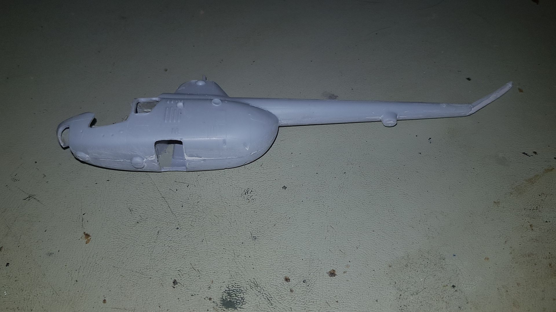
Remember how that tail rotor boom looked after the two halves slipped whilst assembling?
This is how it looks now:
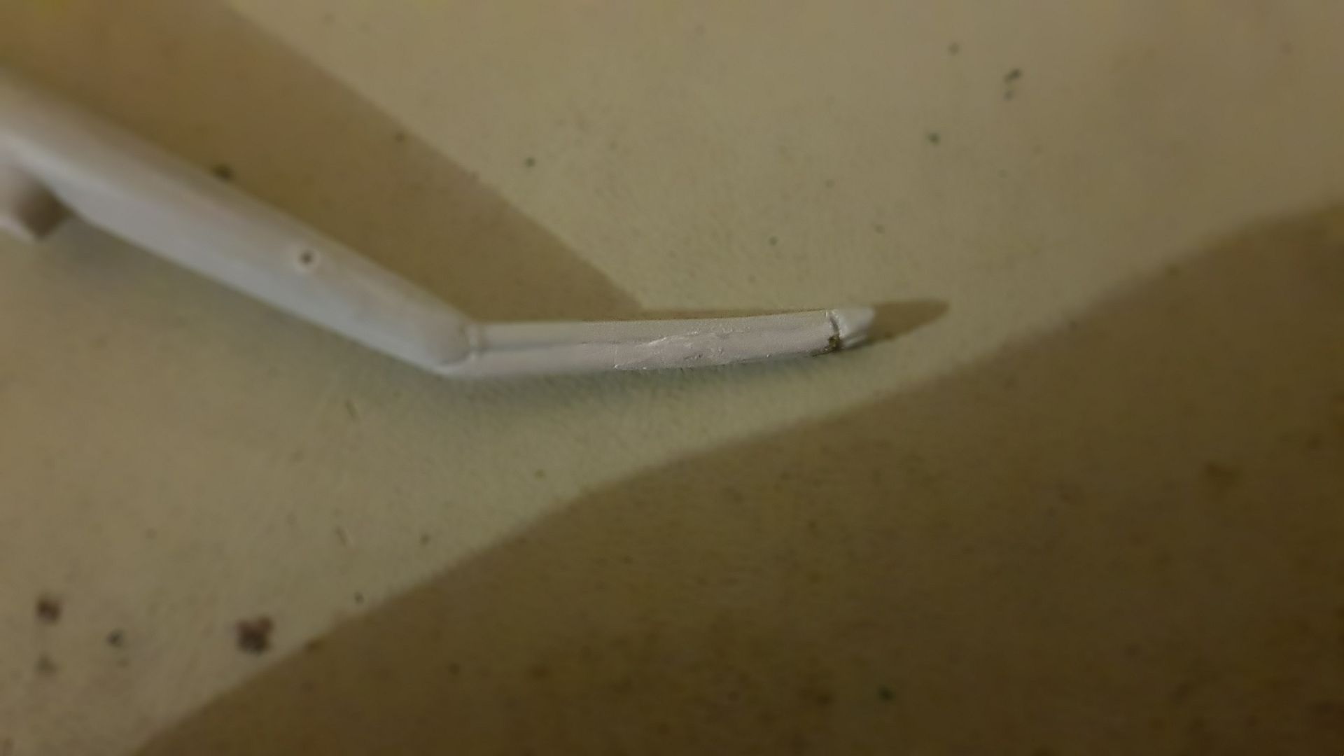
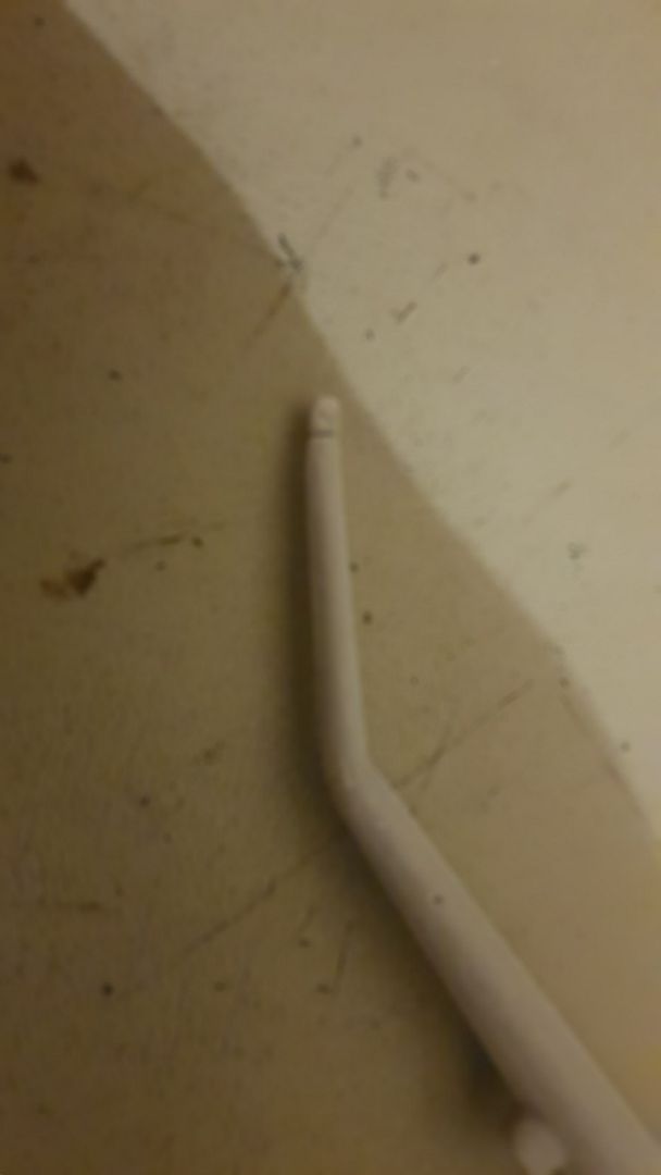
I think a little bit more work is needed but it looks a lot better than it did.
Re: MiL Mi-1
Posted: Fri Dec 13, 2019 7:57 pm
by jmurphy18
Nice fill work here Neil
Re: MiL Mi-1
Posted: Fri Dec 13, 2019 11:04 pm
by digger303
Have another problem like this consider spru goo. It can be smoothed down a lot with more tet and a brush.
Re: MiL Mi-1
Posted: Fri Dec 13, 2019 11:51 pm
by RangerNeil
digger303 wrote: Fri Dec 13, 2019 11:04 pm
Have another problem like this consider spru goo. It can be smoothed down a lot with more tet and a brush.
Did think of this - at the moment though I don't have any tet or equivalent to decant into an empty bottle to melt the sprue into. Funding is - to put it mildly - stretched tighter than a guitar string as our daughter is getting married next year. If - gawd forbid - I get another one like this I will have to take the appropriate steps.
Spent this evening in between sanding the filler down trying to work out what the hell that funny symbol in the instruction means - looks like a round window extraction vent for want of a better description when it comes to assembling the rotor head..

I think it means I have to make up some thin lengths of stretched spue to act as actuator linkages for the rotors - but no length is given and the part no.43 is shown with the legs pointing down so I am not sure, given the rotor is supposed to be free to rotate, that they will clear the top of the pylon. I am assuming right now that the parts indicated by the circular symbol that have no part number are to be fabricated and then stuck in position on one side of the legs on part no. 43 and the equivalent side of the top rotor head, part no. 28 on a trial and error basis. We'll just have to wait and see. - I've change the build plans now so that I do the main rotors last. I now want to finish the fuselage and get all that sorted out then put it to one side and concentrate on the main and tail rotors exclusively.
Re: MiL Mi-1
Posted: Sat Dec 14, 2019 7:41 am
by Johno
Great job beating that ol' bird into submission so far!
Re: MiL Mi-1
Posted: Mon Dec 16, 2019 11:43 am
by Tomcat64
If you don't fancy stretching sprue to make those scratch-built spindly bits could you use short lengths of fusewire or something similar?
Re: MiL Mi-1
Posted: Mon Dec 16, 2019 11:53 pm
by RangerNeil
Tomcat64 wrote: Mon Dec 16, 2019 11:43 am
If you don't fancy stretching sprue to make those scratch-built spindly bits could you use short lengths of fusewire or something similar?
Hmm - never thought of that - thanks!!
Might even make the rotor head a bit stronger.
There are a couple of long thin pieces in the kit that the instructions say "do not use" that could have been cut to length and are about the right dia.
The fun will be getting the right length. The small collar drops over the shaft for the rotors, the rotor head is then stuck on top of the rotating shaft and then the lower collar is joined to the head by these three pieces. So a dimension would have been usefull
(I spent too long as a Toolmaker - gives me bad habits when looking at drawings.
)
Re: MiL Mi-1
Posted: Tue Dec 17, 2019 2:15 am
by RangerNeil
I cut the two parts of the rotor head off the sprue tonight, cleaned them up and tried a dry run assembly:
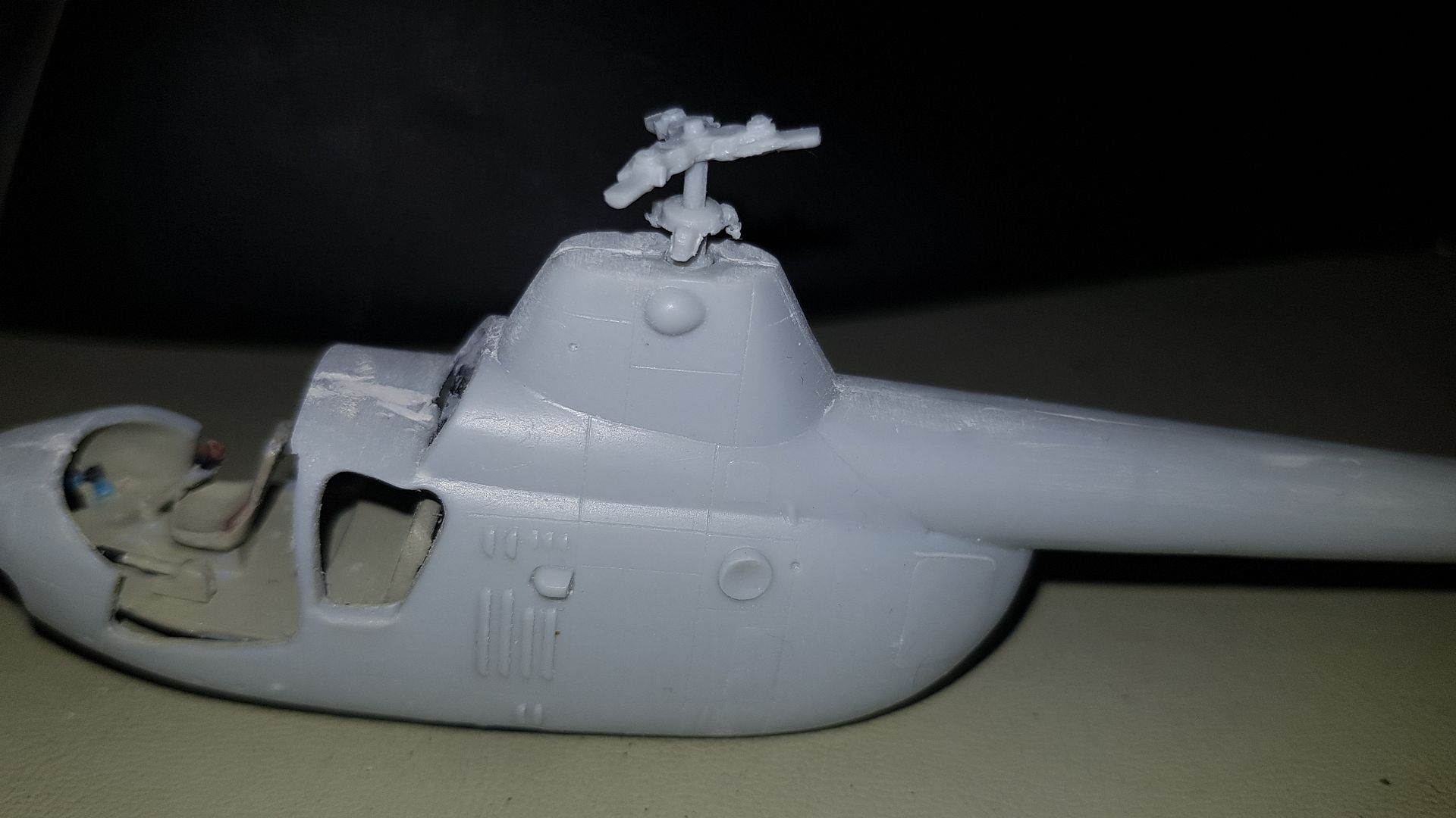
Hopefully the issue of alignment can be seen. I think those 3 lengths need to be about 5mm long - should be assembled off the model, maybe on a drill shaft, and allowed to set before being place on the model.
If it then sits right it can be removed, inverted and the main blades fitted. Like on others builds here I have some worries about the strength of the assembled blades. Once on the model it will be a case of do not touch - indeed, ideally inside a covered case to keep dust off.
On another note - I was ordering some stuff from Amazon tonight (pressies for the daughter Mk 1) and saw this:
https://www.amazon.co.uk/ABEST-Professi ... 85&sr=8-13
Any good for a beginners set-up do you think??